WP's HP: HOME
| SloMo: Links
~ FAQ ~ Info ~ Tips ~
Data ~ Clips
~ HYCAM ~ Freq. ~ [f-Calculator]
~ Trigger ~ Image
RAM | ?Help? | Deutsch 
Easy to use calculator for the distance to object with
given focal length and for focal length with given distance to
object keeping the condition of format filling imaging. Thus making
best utilization of the photoactive area of the imaging medium.
(JavaScript required.)
Please type in a full stop ».« as decimal
punctuation mark and take notice of the different
measurement units.
(By the way: 1 inch = 25.4 mm, 1 foot = 304.8 mm, 1 yard
= 914.4 mm = 0.9144 m, 1 mile = 1 609.34 m)
d: Distance between object scene and camera lens (exact object side located main plane of the imaging system)
f: Focal length inscription on the lens as a rule in millimeters; will be in accordance with reality, if the lens is fit onto the adequate adapter
O: Maximum expansion of the object vertical to the imaging direction; in simple words: what's to be seen. One can select the diagonal as well
S: Minimum expansion of the active sensor area or film vertical
to the imaging direction. One can select the diagonal as well.
Refer to [SloMo Info] for
values.
By the way: the sensors are much smaller than the format diagonal
given in inch seems to claim. Thus a 1 inch sensor has never a
diagonal of 25.4 mm, but just one of 15.875 mm (about 5/8
inch). This ratio can be used as »conversion factor« for other
formats.
2ω: Angle of view or field of view 2ω = 2 × arctan (1/2 × O / d) = 2 × arctan (1/2 × S / f'); with the focal length of the lens f' (not really f of the lens inscription, but the flange-back, because usually a camera lens consists of several lenses); [values in mm].
Caution: One has to keep at least a distance of 0.3 m
(sometimes more than 1 m) using standard lenses, otherwise
they cannot provide sharp images.
By the way the real sensor size can be estimated when transforming
the equations given above. Object size O and object distance d are
just measured in a test set, the focal length f is that of the lens
inscription: S = f × O / (d - f); [all values in mm].
Each of the following terms, i.e. their sum, give the
depth of field (or depth of focus) region where objects are in
focus, thus appear sharp. (All in SI units - meters or
millimeters.)
The in-focus region in front of the set distance is:
dfront = d × f² / (f² + k × Ø × (d - f))
And the in-focus region behind this distance is:
drear = d × f² / (f² - k × Ø × (d + f))
Signs and symbols:
d = set distance on the focus ring
f = focal length of the lens
k = f-stop number
Ø = diameter of the circle of confusion
The diameter of the circle of confusion is given by the minimal
distance of two spots the human eye is able to identify from a
certain distance. A standard value is 2 angle minutes from
250 mm distance, thus 0.0145 mm. Or 6 line pairs per
millimeter as well. (Strictly speaking one has to calculate this
from the output medium to the sensor or film, resp. backwards ;-) A
rule of thumb is: Ø = diagonal of the sensor [in mm] / 1 000
... 1 500.
Setting d to so-called hyperfocal distance h = f × (f / (k × Ø) +
1) makes the region starting at h/2 to infinity appear in focus.
Many simple cameras work in this way.
Estimating the size of the interesting area of moving objects and the occurring velocities, here the equations of movement in simple form. (All in SI units meters and seconds.)
Signs and symbols:
Velocity: v = v(t) [m/s]; t: time [s]; v0 =
v(0)
Acceleration: a [m/s²]; covered way: w [m]
v = v0 + a × t
w = v0 × t + a/2 × t²
2 × a × w = v² - v0²
Signs and symbols:
Angle velocity: ω = 2 × π × f; frequency: f = K / t =
1/T [1/s]; K: count of rounds; t: time; T: duration of one turn;
π = 3,14
Orbital radius: r [m]
Orbital velocity: v = r × ω

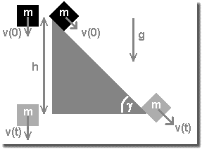
Free fall and inclined plane
Basic principle is the conservation of energy: Epot = Ekin. Hereby the mass of the object is abridged. Friction is supposed to be negligible. And - important - the object must not significantly gather rotation energy, thus it should preferentially glide down the ramp without much friction. (But for a car - model or real - the formula works.)
Signs and symbols:
Potential energy (energy of level): Epot = m × g × h; m: mass of the object; Earth gravity acceleration: g = 9.81 m/s²; h: dropping level or altitude of the inclined plane, resp.
Kinetic energy (energy of movement): Ekin = m/2 × v²; m: mass of the object; v: velocity of the object at impact, i.e. after falling the distance h, or when leaving the inclined plane
v = √(2 × g × h)
h = 1/2 × v² / g
Every theory finds its challenge in reality...
During exposure the object moves the distance
Δw = v × tshutter
the product of its velocity and time of exposure of each
frame.
Example: A car moves with constant velocity v = 64 km/h =
17.78 m/s. With a frame rate F = 1 000 frames/sec the car
will change its position in one frame up to
Δw = v × t = v / F = 17.78 m/s / 1 000 frames/sec = 0.01778 m = 17.78 mm
if one does not reduce the time of exposure for each frame by using a shutter. If the image of Δw is smaller than one pixel, the effect will not be visible.

Stretching resolution by cross movement
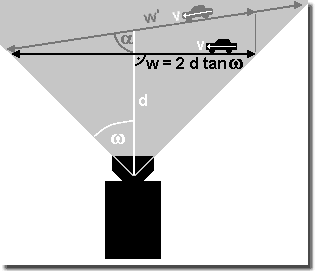
If the camera does not perpendicularly look onto the object, but an angle different from 90° lies between camera view and object or its direction of movement, resp., e.g. if a vehicle moves towards the camera, thus the distance to be caught is reduced to about
w|_ = w' × sin α
with w|_ as perpendicular component of the drive path w' and the angle α between viewing direction and vehicle drive path w'.
As the figure on the right shows one is possibly
able to gain some more path when selecting an appropriate
setup.
So one has the chance to capture more details in space and time,
thus imaging the object and its movement in higher resolution.
In this setup, however, one must take in consideration depth of field, because the distance to the camera may heavily change.
©WP (1998 -) 2012
http://www.fen-net.de/walter.preiss/e/slomo_f.htm
Update: V8.4, 2012-03-02